roger
New Member

Posts: 17
|
Post by roger on Nov 5, 2023 21:46:22 GMT -5
I recently saw a TX750 converted to Dyna S ignition. The engine had very smooth low RPM idle and excellent throttle response. The conversion included fabricating a base plate from 0.1" thick aluminum and modifying the rotor to work with the original TX750 ignition advance.The rotor was of single magnet type and required an internal bushing to increase its length and decrease internal diameter to match the TX750 rotor size, and two new notches for the TX750 centrifugal weights. The Dyna ignition fit right into the old breaker plate space, the wires hooked up directly to the stock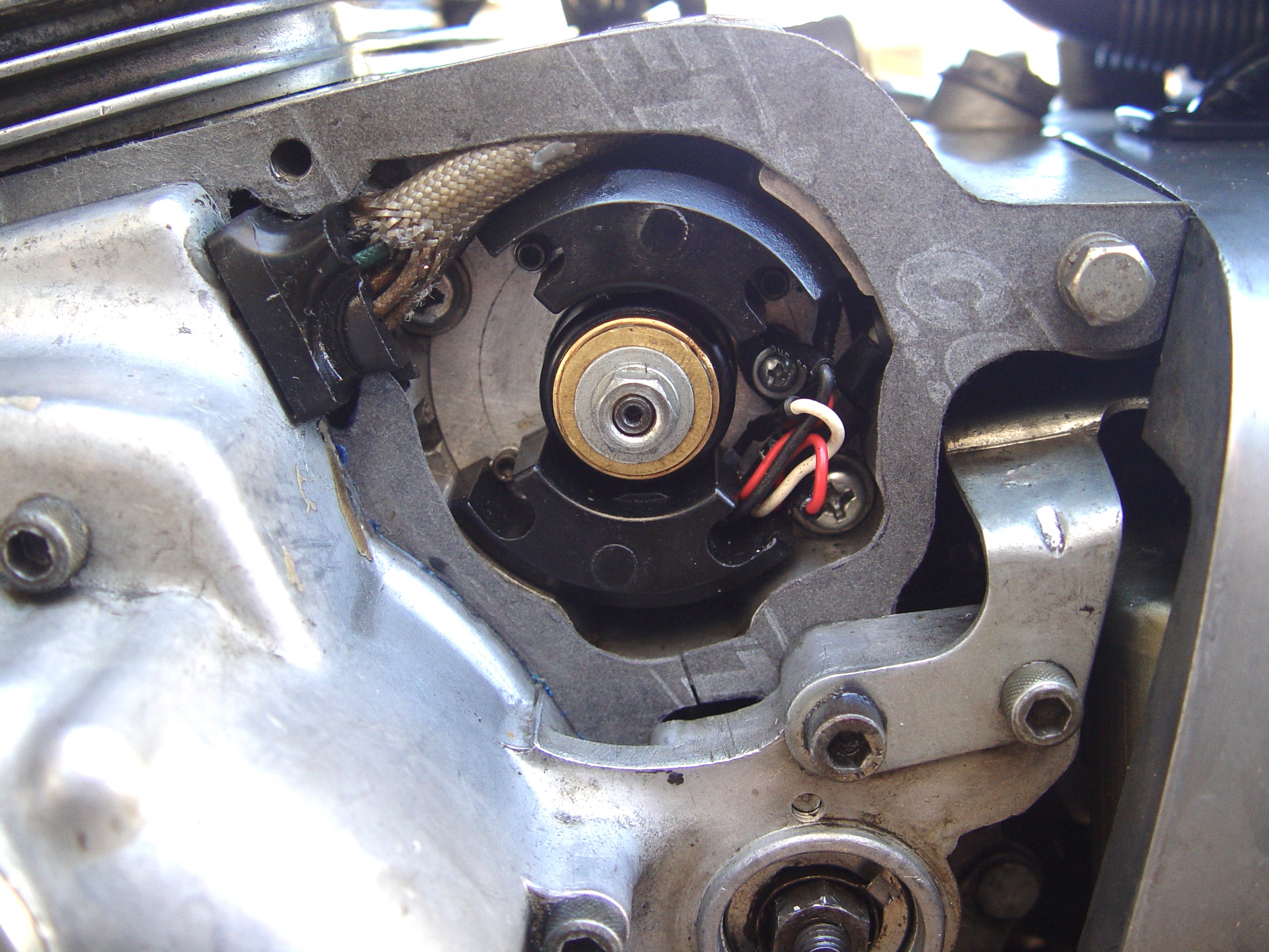 ignition coils, omitting the capacitors. ignition coils, omitting the capacitors.

|
|
sos
New Member
Posts: 10 
|
Post by sos on Jan 15, 2024 8:42:56 GMT -5
That is very interesting. I’m doing 2 TX750 builds right now and am looking at adapting an old Pamco ignition or XS Charge ignition from a XS650.
The ignition plate bolts right in with only relieving the plate to allow the securing screws to thread into the case.
It’s the advance mechanism that I was wondering about. Sounds like it has already been done. I’d love to see the drawing for the bushing adapter.
|
|
roger
New Member
Posts: 17
|
Post by roger on Feb 16, 2024 12:08:02 GMT -5
|
|
roger
New Member
Posts: 17
|
Post by roger on Mar 7, 2024 16:20:25 GMT -5
The bushing is made from bronze stock. It needs to sit firm inside the rotor with a slight press fit and rotate with little play on the ignition advance shaft. The overall length of rotor including bushing is 31.4 mm. You should leave the bushing collar fat enough to allow for some material removal after press fitting the bushing into the rotor, in order to end up with exactly 31.4 mm length. The rotor and pick up coils used here are from a Dyna-S ignition made for 1973-84 Z1-900, KZ 900 and KZ 1000, other rotors may require a different collar thickness. Dyna-S pick up coils come in slightly different variations, depending on the year. One kind drops right in, the other needs some filing. This will be discussed later, when I will also point out how to add two additional slots in the rotor to fit the TX750 centrifugal weights. The rotor also needs to have an internal groove, 17 mm diameter and 3 mm wide, to accommodate the retainer pin pressed into the advance unit shaft.  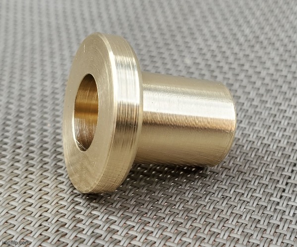 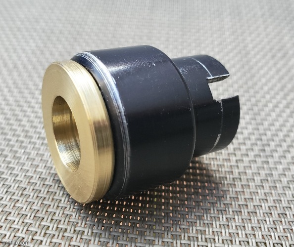 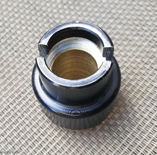  Above is a sectional cut of the modified rotor assembly. The grey part is the rotor, the yellow part is the bushing. This all can be fabricated on a low end hobby lathe. |
|
roger
New Member
Posts: 17
|
Post by roger on Mar 12, 2024 0:34:30 GMT -5
The support plate for the Dyna-S ignition modules is machined from 3 mm aluminum. The inner diameter is 28 mm, the outer diameter is 61.9 mm. The plate needs to fit snug but not tight into the recess where the breaker plate used to be. The four screws holding the Dyna modules are located on a 46.13 mm diameter circle. Drill and tap as shown in the pictures below. One more hole needs to be drilled and tapped for the wire clamp, but not too close to the adjacent mounting hole. Two 13 mm wide relief cutouts need to be filed to clear the breaker plate mounting screws, starting with the one closest to the module mounting hole on the right side of the picture below. This is a hand fitting process and several installations and removals of the plate are to be expected in the process. 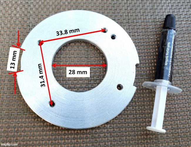  The Dyna modules should be installed using thermal grease normally used for CPU's, for better heat sinking. There are three kinds of Dyna-S modules on the market, the old bulky ones shown in the picture and the newer flat ones with the Hall element sticking out. The latter ones won't fit because their bases are too wide (they will work perfectly for YR5, DS7 and RD models, though). The bulky ones come in two versions, one where the module's metal base plate is visible (see picture) and one where it is hidden under plastic. For the latter one to fit into the tight space, some or all of the plastic covering the base needs to be filed off. 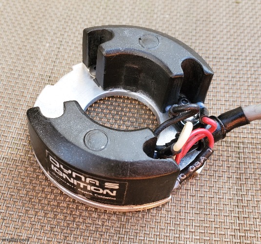 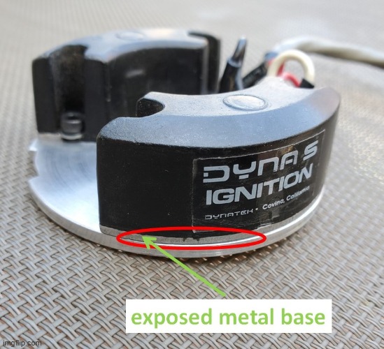 In the next step, the locations of the additional cut outs in the rotor need to be determined. First, the ignition advance weights are removed and a radial line is scratched into the backing plate, in line with the retainer pin (the pin coincides with the location of the small actuator arm of the centrifugal weight for maximum advance). Slip the rotor onto the advance shaft, install the advancer assembly on the oil pump shaft. Put a washer with a 15+ mm hole between the rotor and the factory nut and washer securing the rotor. Hand tighten the nut until the rotor does not move anymore when turned by hand. At this point the Dyna assembly will also be installed. Temporarily plug the Dyna modules into the harness connectors for the old breaker plate assembly right next to the oil filter. Lift the seat up and look on the left side right next to the tank for a two prong connector with two black wires leading to the condensors hidden behind a couple green resistors. Unplug the condensors and tuck the connectors away. Remove the spark plugs and remove both inspection screws from the alternator housing. One screw allows access to the crank bolt, the other one gives access to the timing marks on the flywheel. Rotate the crankshaft counterclockwise until the max. advance mark lines up. Static ignition timing is used to adjust timing plate and module location. A timing light, ideally positioned close to the timing mark hole, is connected to ground on one side and to either the white or black wire from the modules, right where it plugs into the harness. Connect the red wire of the Dyna ignition to the positive battery terminal and turn the ignition on. Now slightly loosen the rotor nut and spin the rotor manually counterclockwise until the light comes just on. Tighten the nut, put a 17 mm socket on the crank bolt and slowly rotate the crank 2 revolutions counterclockwise until the lights comes on again. Adjust the rotor until it always lights up at the max. advance mark. Now connect the timing light to the other module and repeat the process. If timing is off, only the module connected to the timing light is supposed to be adjusted. After both modules are timed correctly, remove the Dyna assembly to have access to the rotor. Mark the area where the rotor rests on the ignition advance back plate with a couple dots of nail polish and let dry. Unscrew the rotor nut and remove the entire advance assembly. The rotor will now spin on the shaft but the nail polish dots will aid in positioning it back to where it was when ignition was timed. Once positioned back correctly, find the line previously scratched into the back plate. Mark the rotor at the same location. This will be the center of the new slot engaging with the advance weight. The ridge between the old and the new slot should be no less than 6.6 mm wide, 6.8 mm is a good number from experience.   |
|
